LED Fan mini guide
Since I feel like I'm winding down to the end of my mod (and the strong feeling that I'll be completing this soon, I mean, my god haven't I procrastinated enough?), I've been doing some small things to kill time. Must be the fear of failure in me that I need to find other projects instead of just completing the one that I have - lol.
Anyway, I had picked up some of
these as a good way to add a little wiring to my case, and I figured, what the hell they're YATES! Right? In my mind, my concept originally started as a more
BLING and less
ZING, but as time has progressed, I've come away from that and want to be more low key.
But why the
LED fans then? Well, what if I could
turn it on and off? With a little help, I was able to make a simple
LED fan mod that I figured I could share with those here: so here goes.
LED FAN mini guide
When you peel the sticker off of the Yates, you're left with this:
It's a
circuit style
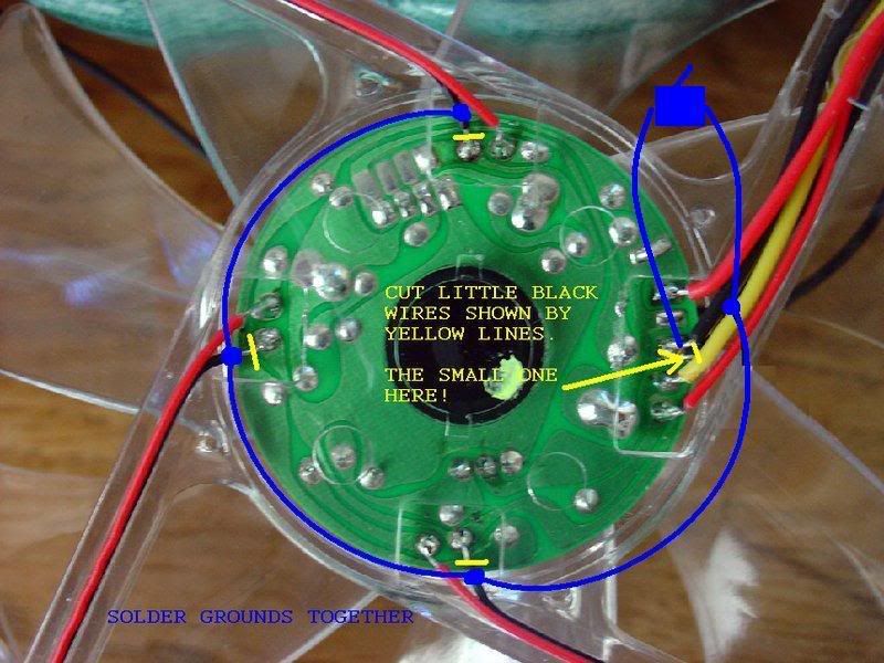
LED fan which means that I have to connect the wiring together and then bring the power to an external switch that I can control. Here's the idea:
borrowed from Lost-Modder-thxs!
STEP 1
I began by cutting all the black wires as instructed that connected the
LED's to the PCB board. The picture shows a wire cutter being used, but this was for illustrative purposes only; I ended up using an Art Razorblade Knife (or Exacto or whatever it's called) as the wirecutters would not fit into the small area's that were not covered by plastic.
(pic A)
STEP 2
After cutting all wires I began on the side just after the main connection area so that I would end there. I began by soldering the 2 ends together, and then using the smallest heatshrink that I had. A Heat Gun is highly recommended for this. I next coupled the middle of the wire to the next end, thus saving solder steps. To do that, I cut the rubber off with the razor exposing the bare wire (pic B). I then used a slightly larger heat shrink to safeguard this coupling and moved on to the next junction. Progress is shown in pic C. and pic D.
(pic B)
(pic C)
(pic D)
STEP 3
After completing all the
LED's, I ran the wire down the
fan channel by the main
circuit area. I then connected a new ground wire to the main connection where the
LED wire was earlier. I also ran this wire down the same channel. I used a very slim piece of electrical tape to hold the wires in place. I may substitute this for hot glue later. At this point, I connected the two black wires to a non-led rocker switch. With the wires connected, I turned on the
fan via my PSU (also jumping the PSU by connecting a wire from the green connection to a black/grnd connection on the 24 wire molex). It worked and the
LED's were off (pic E)! I then put the
LED's on using the switch (pic F), and that worked as well! I then turned it off and on for the next few minutes while patting myself on the back. Very happy with the finish here.
(pic E)
(pic F)
STEP 4 - GO NINJA!
Here's my semi-lame attempt at hiding my work, and I may change this in the future with just black elect. tape, or whatever I may find. But for now, I think it looks good from outside the case, but if you were right up on the
fan, you would notice that something wasn't quite right.
What I attempted to do was burn a groove in the plastic to tuck the wires in. The problem that arose was I was nervous about going to far and dripping plastic onto the
circuit board. So I only went down about halfway which left the wire slightly on top of the cover. Also, my wiring itself had been a tad too short, so that the loop isn't perfect or a perfect circle, it pulls a little in.
After the groove was cut, I reapplied the sticker and that's what you see in the last picture (pic G). What's left to do is sleeve the exposed wires with black sleeving, and then decide where the switch will go.
(pic G)
I didn't take any pics of the rocker switch, but this is simple to do if anyone wants to see that. If there are other pic requests, just ask as I may do 1 more
fan and can take more pics.
Again, thanks for the help, and I hope this mini guide helps you!

")
")